Measuring with Photography
TRITOP Professional software is used to analyze the high-resolution images produced by the TRITOP measurement system. Features such as reference points, contrast lines and adapters are determined quickly and accurately, and displayed in the software including the calculated 3D coordinates. The TRITOP measurement system and the matching software can be used to measure and inspect not only small components but also larger parts such as are used in the construction of trains, ships and wind power units.
From 3D Coordinates to Full Inspection-Complete work process in a single software
Combining the TRITOP system with the TRITOP Professional software makes it possible to process 3D point coordinates. A user-friendly graphical interface enables operators to process and evaluate the measurement data. The TRITOP software supports work in quality control and component testing in the field of modern development and manufacturing processes. The basic software functions include capturing measurement points and processing them to model 3D point clouds as well as monitoring image quality. Tools such as CAD data import, the import of measurement plans, alignment, point deviations from CAD, calipers, angles and diameters, vector fields, GD&T analysis and reporting are available for the purpose of quality control and results analysis.
Feature Highlights
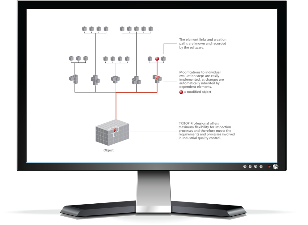
Parametric Inspection
Parametric inspection is a tried and proven software concept in which each individual element retains its path of creation. All evaluation steps can be traced and therefore easily modified and adjusted. A one-button solution updates all dependent elements automatically after changes have been made. Parametric inspection is also used on numerous data records for trend and deformation analysis. This makes it easy to analyze several components or stress phases within a single project. With the TRITOP measurement system and full parametric inspection, GOM has therefore standardized the function base for deformation analysis.
Deformation Analysis
Evaluation features are available for the deformation analysis of points. They define and analyze motions and deformations on the basis of a component concept. To make this possible, inspection points are divided into coherent groups. Transformations or corrections to rigid body movements can then be calculated for these components.
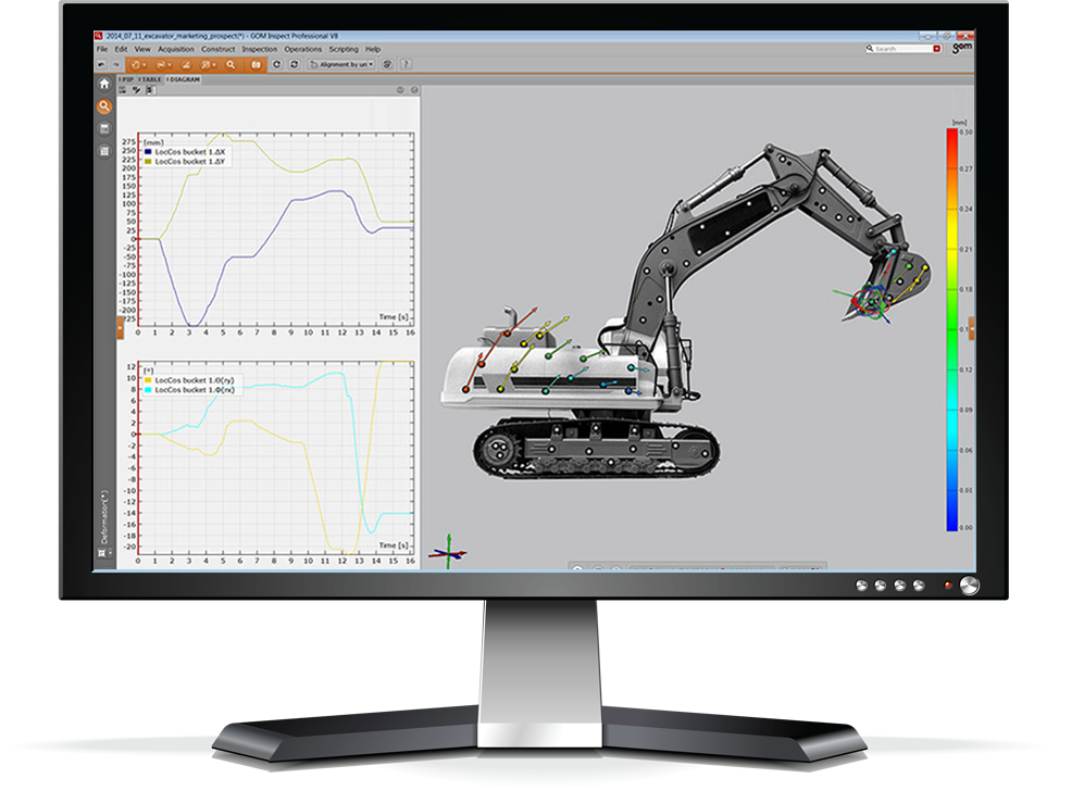
Image Mapping
TRITOP Professional offers optimal orientation during measurements with its image mapping and 3D views. In addition, image mapping also allows fast and easy project navigation during analysis. Individual color-coded CAD deviations and vector displacements can be visualized easily within the color images. So that operators can work with a specific image during all work phases, an image from one stage can be displayed through several stages in TRITOP multiphase projects. Image mapping is therefore one supporting element in the presentation of results.
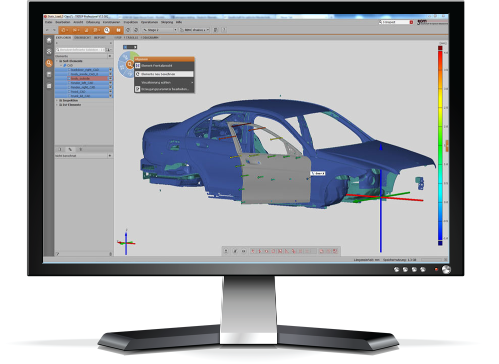
I-Inspect
I-Inspect stands for intelligent inspection and guides operators through the inspection process. TRITOP Professional makes it easy for them to assign measurement principles and testing specifications. Additional freely configurable inspection principles are available via I-Inspect. The software can be operated via a single button and therefore helps simplify the entire process, so that inspection tasks can be performed at speed.